
System Planning and Definition
Water Bottling System Process Flow and Equipment Interfaces
A useful system flow map overlays material, utility, information and evidence paths so one machine boundary is not reviewed in isolation from the conditions that enable it.
Decision focus
Where do product water, containers, packaging materials, utilities, machine states and evidence cross the same system boundaries?
01
Direct Answer
A useful system flow map overlays material, utility, information and evidence paths so one machine boundary is not reviewed in isolation from the conditions that enable it.
Planning essentials
Water Bottling System Process Flow: Six Paths to Map Together
A practical answer for buyers comparing equipment, scope and connected-system requirements.
The visible production sequence moves from product-water preparation and container supply through filling, coding, labeling, packing and pallet transfer. A working system also depends on utility, control and verification paths that cross the same equipment boundaries.
The Allot Tech Beverage Bottling Catalog 2026 shows water-treatment, bottle-production, rinsing-filling-capping, labeling, coding, conveying, packing and pallet-handling categories. The final sequence and included equipment must be selected from the actual water, bottle, pack and site basis.
Product-water flow
Treatment, storage, transfer, release and filler demand must use one operating basis.
Container and closure flow
Preforms or bottles, caps and change parts need controlled identity and release conditions.
Packaging flow
Labels, codes, film, cartons, pallets and rejected packs require defined handoffs.
Utility, state and evidence flow
Terminal conditions, machine states and proof records enable the physical process to run and recover.
System scope
Process Stage, Equipment and Interface Questions
Use the flow to identify the next boundary that needs project evidence.
Scroll the table sideways to read every column. With a keyboard, focus the table and use the left or right arrow key.
| Process stage | Applicable equipment functions | Interface question to close |
|---|---|---|
| Prepare product water | Pretreatment, membrane treatment where required, disinfection, storage and transfer. | What condition and usable supply must be available at the filler inlet? |
| Supply containers | Bottle blowing, unscrambling, depalletizing or controlled manual feeding. | Which approved bottle reaches the filling section, in what condition and machine state? |
| Rinse, fill and close | Rinsing, filling, capping and cap feeding. | Which product, bottle, cap, utility and permissive conditions enable filling? |
| Identify and inspect | Coding, labeling and applicable inspection or reject functions. | How are format identity, code or label presence, reject and recovery coordinated? |
| Pack and transfer | Collation, shrink or case packing, conveying and pallet handling. | What stable pack condition and downstream availability allow transfer? |
| Stop, recover and verify | Cross-machine states, alarms, controlled restart and connected tests. | Who owns the response, which prerequisites permit restart and what evidence closes the result? |
Practical review
Worked Flow Review: A Downstream Packer Stops
Illustrative event sequence for a filled-bottle conveyor and packer. The purpose is to make stop propagation and recovery explicit; exact timing and safety functions require the approved machine design.
Scroll the table sideways to read every column. With a keyboard, focus the table and use the left or right arrow key.
| Observed event | Cross-machine response to define | Record during the connected test |
|---|---|---|
| Packer stops accepting bottles | Identify which downstream-ready or blocked condition changes and who owns it. | First event timestamp, state and signal quality. |
| Usable accumulation is consumed | Define the upstream hold request and which machines respond before the transfer is overloaded. | Conveyor state, occupancy observation and upstream response. |
| Filling pauses | Coordinate the product-water demand or circulation response with the filler supplier. | Water-system state and product-hold decision. |
| Packer fault clears | Verify readiness and the approved restart conditions before releasing bottles. | Reset authority, restart permission and bottle spacing. |
| Stable production resumes | Check label, code, closure and pack acceptance according to the test plan. | Rejected/accepted counts, recovery observations and open deviations. |
A process-flow drawing should connect each material arrow to the signals and owners that stop and restart that transfer. Do not infer safety interlocks from an ordinary production-ready signal.
02
Position in the System
This page maps intersecting interface flows and does not retell the complete source-to-pack production process. It controls the boundary between Buyer requirements, approved product formats and available site records and A coordinated mixed-vendor system definition for technical review. It excludes a generic production-process encyclopedia and operating manual.
03
Buyer Inputs
- The buyer decision to close: Where do product water, containers, packaging materials, utilities, machine states and evidence cross the same system boundaries?
- Current drawings, data and operating records from Buyer requirements, approved product formats and available site records.
- Approved terminal requirements and failure behavior from A coordinated mixed-vendor system definition for technical review.
- Project evidence for closure: current process diagrams, architecture records, signal lists and evidence requirements.
- Named buyer, supplier and local owners for assumptions, actions, review and final approval.
04
Interface Map
One controlled record for the physical, process, utility, control and evidence boundary.
SystemInterfaceCard
Water Bottling System Process Flow and Equipment Interfaces
- Upstream system
- Buyer requirements, approved product formats and available site records
- Downstream system
- A coordinated mixed-vendor system definition for technical review
- Transferred material
- Product, container, packaging, utility, state and evidence flows at each active boundary
- Physical connection
- The documented physical, process, utility, signal or evidence boundary covered by this topic.
- Required condition
- Every flow has a source, destination, required condition and stop or hold response
- Utility requirement
- Only equipment terminal conditions are recorded here; plant distribution and local code design remain with the responsible local parties.
- Control signal
- Availability, ready, hold, stop, fault, reset and restart information as applicable to the boundary
- Failure response
- A material flow appears continuous while the utility or machine-state dependency that enables it is missing. Hold the affected decision or operation until the named owner confirms the recovery basis.
- Evidence required
- Multi-layer interface flow map, supported by current process diagrams, architecture records, signal lists and evidence requirements.
Equipment Context at This Boundary

Equipment Used Across This System Scope
These images identify equipment categories and connection points. Final model and configuration selection remains project-specific.

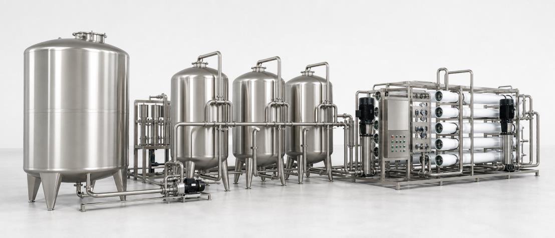
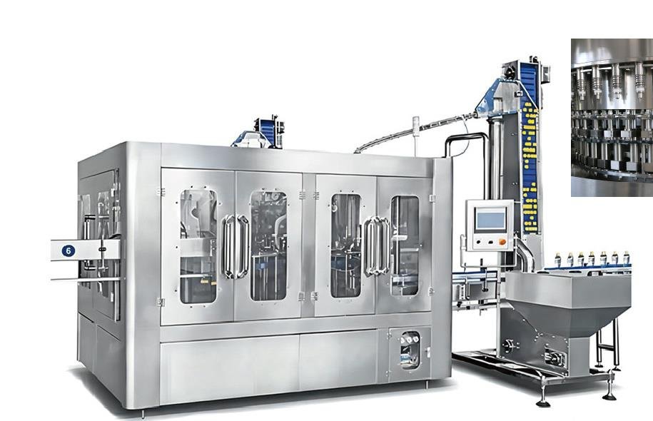
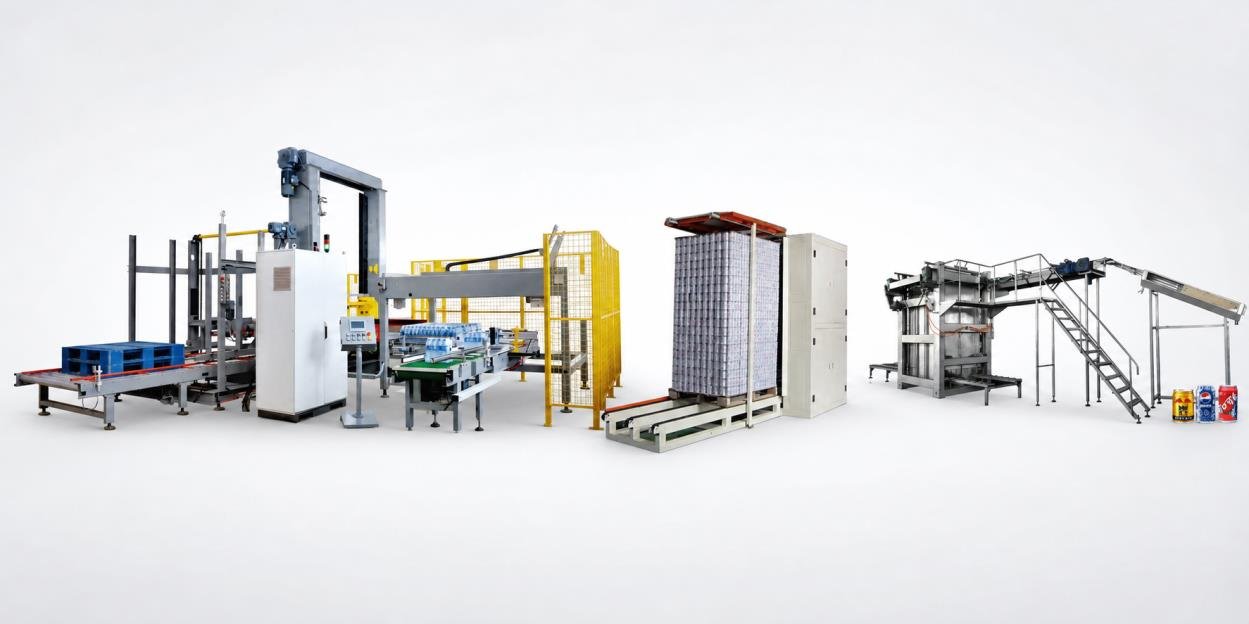
Catalog reference image used to explain equipment and system interfaces. It is not a fixed package or a completed customer project.
05
Main Design Decisions
Decision basis
A useful system flow map overlays material, utility, information and evidence paths so one machine boundary is not reviewed in isolation from the conditions that enable it.
Boundary and handoff
Record Product, container, packaging, utility, state and evidence flows at each active boundary between Buyer requirements, approved product formats and available site records and A coordinated mixed-vendor system definition for technical review.
Required condition and ownership
Every flow has a source, destination, required condition and stop or hold response. The buyer owns the operating requirement; each supplier owns its machine data; the system coordinator maintains the shared interface record.
Closure artifact
Maintain the multi-layer interface flow map against current process diagrams, architecture records, signal lists and evidence requirements and preserve the approved revision.
06
Trade-offs to Resolve
Define now vs. carry an assumption
Closing this decision early can narrow supplier interpretation. Leaving it open may preserve options, but the assumption and later decision gate must be visible.
Local machine simplicity vs. system coordination
A broader early definition can expose more gaps, while a narrower definition can move decisions faster. The chosen boundary must remain explicit.
Broader scope vs. controlled boundary
It excludes a generic production-process encyclopedia and operating manual. Keep the page focused on the evidence needed for this one system decision.
07
Common Failure Modes
These are realistic review scenarios, not claims about a completed project.
- A material flow appears continuous while the utility or machine-state dependency that enables it is missing.
- The upstream and downstream parties use different product, format, operating or revision assumptions.
- The required condition is described but no party owns detection, response, reset or approval.
- The interface is accepted from a catalog or nominal value without current project evidence.
- A drawing or successful local machine test is treated as proof of the complete connected behavior.
08
Required Documents
- Multi-layer interface flow map with owner, revision and status
- Approved design-basis register
- Current equipment and interface list
- Open-input and decision log
- Revision-controlled supplier data
09
Questions to Ask Before Quotation
- Where do product water, containers, packaging materials, utilities, machine states and evidence cross the same system boundaries?
- What exact material, condition, signal, document or decision crosses this boundary?
- Which party detects a missing condition, owns the response and authorizes recovery?
- Which current document, sample, measurement or witnessed result will close the multi-layer interface flow map?
- Which unknown remains open, who must confirm it and before which project decision?
Project-Specific Confirmation
This guide is an engineering interpretation for early coordination. The final multi-layer interface flow map, equipment arrangement, terminal conditions, responsibilities and acceptance criteria require current project data and written approval by the applicable buyer, suppliers and local responsible parties.
11
Related System Pages
Questions
Questions About This Interface Decision
What decision does this Water Bottling System Process Flow and Equipment Interfaces guide help close?
A useful system flow map overlays material, utility, information and evidence paths so one machine boundary is not reviewed in isolation from the conditions that enable it.
What should a buyer prepare for this review?
Prepare current project drawings, supplier records, reference samples or measurements relevant to the boundary, plus the owner and revision of each item.
Does this page approve a final design or supplier claim?
No. It organizes the decision and required evidence. Final engineering, equipment, performance and acceptance depend on the actual project and written confirmation.
Turn the unknowns into a reviewable interface
Review My System Process Flow
Share the available bottle, output, site, utility and supplier evidence. Open items can remain explicitly marked for confirmation.